The design of the heat treatment process equipment not only affects the quality of the workpiece after treatment, but also affects the service life and efficiency of the heat treatment equipment. Most of the traditional heat treatment process equipment design relies on empirical data, with large amount of work, long cycle, low efficiency, high cost, lack of scientificity and predictability. With the wide application of computer technology in the field of heat treatment, computer simulation of the process can reduce the number of experiments, improve efficiency, optimize the allocation of resources, and transform the design of heat treatment process equipment from experience type to scientific calculation type, and improve heat treatment process equipment. The scientific and precise design.
In this paper, through the recent research examples of quenching tank design, carburizing furnace design and process design of large workpieces under the constraints of equipment using computer simulation technology through the research center of heat treatment and surface modification engineering technology of Shanghai Jiaotong University, computer simulation The application potential of the technology in the heat treatment process equipment towel is explained.
I. Simulation and improvement of flow field in quenching tank
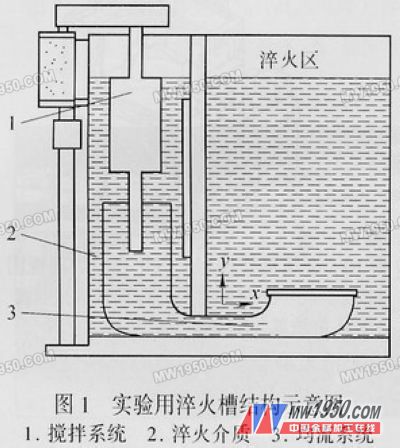
The flow of the medium in the quenching tank directly affects the quenching quality of the workpiece. Uniform flow field distribution ensures uniform quenching of the workpiece and reduces quenching deformation. How to ensure the flow strength and uniformity of the medium in the quenching area of ​​the workpiece is the key to the quenching tank. Figure 1 is a schematic view of the structure of a quenching tank. The finite element method is used to simulate the flow of the medium flow field in the quenching tank, so that the effect of the structural change can be intuitively understood. Figure 2 shows the flow field distribution in the case where the quenching tank bottom is not provided with a flow equalization plate. It can be seen from the velocity cloud diagram that a large eddy current appears in the middle of the flow field, which is not only unfavorable for the heat exchange between the workpiece and the quenching medium, but also has a great influence on the quenching uniformity. In order to prevent the occurrence of eddy currents, a current sharing plate was designed, and the influence of the shape of the flow plate on the flow field distribution was studied.


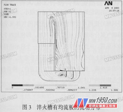
As shown in Fig. 3, the arrangement of the equalizing plates eliminates the eddy current shown in Fig. 2, but there is still a small eddy current generated near the current sharing plate; from the flow field velocity distribution, the fluid flow in the quenching tank is not very ideal. Figure 4 shows the flow field distribution after the improved flow plate. As shown in Figure 4, no eddy current is generated in this design, and the fluid flow rate is relatively uniform.


Next page
Pneumatic Ball Valve,3Pc Ball Valve,Sanitary Ball Valve,Threaded Ball Valve
WENZHOU FOREVER CLASSIC TECHNOLOGY CO.,LTD , https://www.fballvalve.com