“Which is better for triggered probes and scanning probes?â€
“Is the scanning probe more accurate?â€
These problems not only make the users who are in contact with the CMM for the first time, even those who already have multiple three-coordinates, or even those who are engaged in the sales of CMMs, are confused. In the process of selecting a three-coordinate probe, it often happens that the configuration is ultimately determined by the budget, resulting in an over- or under-configured situation.
When we configure the probe of the CMM, we actually face difficulties in selecting from many aspects, such as “fixed or rotaryâ€, “scanning probe or triggering probeâ€, “three-axis linkage or five-axis linkageâ€. ", "contact probes or optical probes" and so on, and ultimately can not escape the budget constraints. Although the last factor can sometimes play the role of one-vote veto, it is necessary to understand the characteristics of the various types of probes and the applicable occasions and limitations from a technical point of view, so that the most suitable probe can be selected under the comprehensive conditions. Measurement requirements.
[trigger probe and scanning probe]
In fact, to examine the difference between the trigger probe and the scanning probe, it is necessary to proceed from the characteristics of the measurement task. As we all know, the coordinate measuring machine is capable of performing all-round measurement from size to shape tolerance, and is a general-purpose detecting device. However, a single size measurement, such as length, diameter, angle, etc., can basically be measured by a simple gage. The three coordinates are not irreplaceable significant advantages; while the measurement of behavioral tolerance involves many aspects, such as measurement datum. , the fitting method, the measurement principle, etc., must rely on the coordinate measuring machine as a systematic whole, which is the main reason for the irreplaceability of the coordinate measuring machine.
As the name implies, geometric tolerances actually contain two different types of elemental feature evaluations, one is shape tolerance and the other is position tolerance. Shape tolerances include straightness, flatness, roundness, cylindricity, line profile, and face profile; and position tolerances include parallelism, perpendicularity, slope, position, concentricity, concentricity, and symmetry. . In addition, there is a special type of geometric tolerance called bounce, including radial/face round runout and radial/end face full runout. Bounce is essentially an evaluation of the shape error of the measured element, so we may wish to classify it as a shape error.
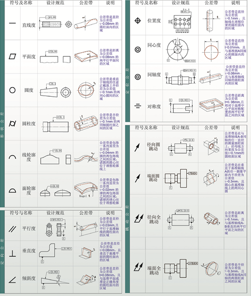
We take a measurement of a circle as an example to evaluate its diameter, position, and roundness. As is known, the minimum number of points required to determine a circle is three, so that a theoretical circle can be fitted and the circle has a roundness of zero. In the actual measurement, it is rare that the measured circle is determined using only 3 points. Even for non-critical sizes with large tolerances, at least 4 points are collected to determine the circle to be measured, so as to avoid large errors due to interference factors. It is true that for a circle with a uniform distribution of single-point errors (no singular points with mutations), measuring 4 points, 8 points, or 12 points has little effect on the final diameter and position (it is not too tight in the tolerance band). In small cases), especially for circles obtained by least squares fitting; however, the effect of the number of points on roundness is not negligible. According to the analysis and calculation of the system, the number of measuring points required to accurately evaluate the roundness of the circle to be measured is not less than 64 [1].
This number of measuring points gives us a clear indication that if the measurement requirements of the part to be tested have a measurement requirement for roundness, then a scanning probe is required. Imagine that if the 64 points of a circle are measured using a single-point touch probe, the measurement efficiency is obviously unacceptable. From the measurement efficiency and rationality, in fact, not only the roundness, but also other types of shape tolerance measurement should use continuous scanning probe, otherwise it is difficult to accurately evaluate the shape tolerance of the measured element.
According to the above analysis, can it be understood that the scanning probe is an upgraded version of the triggering probe, and the scanning probe is selected as much as possible under the premise of the budget? The answer is also negative. When the scanning probe performs a single-point triggering point, its working mode is quite different from that of the triggering probe. The pick-up probe's pick-up point occurs at the beginning of the probe trigger; the scan probe uses analog signal conversion, and the single pick-up point occurs when the probe triggers and the stylus leaves the surface of the object. The most obvious difference between these two different points is that the trigger probe is significantly faster than the scanning probe. The point of the triggering probe is “one touch and retreatâ€, while the scanning probe picking point is that after the stylus touches the workpiece, it will temporarily stick to the surface of the workpiece and then slowly retreat to the surface of the workpiece. Therefore, when there is no scanning measurement requirement, the triggering probe is more efficient in measuring efficiency than the scanning probe.
It is also worth mentioning that some specific functions must be realized by scanning the probe, such as “self-centeringâ€. The “self-centering†application is generally used to find the center point of the small hole, the bottom of the groove, etc., which requires the probe to have a search function until the analog signal of the probe reaches a stable state. Picking point, this function is impossible to achieve with the "one touch and retreat" trigger probe.
[Fixed probe and rotary probe]
Again, this is not a good or a bad proposition, but just the difference in design intentions that lead to differences in the application. The most significant advantage of a fixed probe compared to a rotary probe is its stylus carrying capability. Due to the inherent advantages of its structural design, the fixed probe generally allows the maximum weight and length of the stylus to be carried significantly larger than that of the rotary probe. Therefore, in the case of deep hole measurement and large part measurement requirements, it is more common to select a fixed probe. However, when we are performing more complex measurement tasks, because the probe cannot change the angle, it is necessary to configure the suction cup according to different stylus directions. Therefore, for a three-coordinate measuring machine equipped with a fixed probe, a double-layer or even a three-layer needle changing frame is very common, and the needle changing action during the measurement process is also quite frequent. The rotary probe came into being to overcome this weakness of the fixed probe. The pitch and yaw function of the probe head can greatly improve the measurement flexibility without changing the needle, but the flexibility of the rotary probe While improving, it sacrificed part of the stylus carrying capacity.
There is a view that the accuracy of the fixed probe is higher than that of the rotary probe, which is somewhat partial. Indeed, for metrology-level geometry measurements (sub-micron), high-precision fixed probes do take an absolute advantage; but for conventional applications, and without measurement requirements such as deep holes, fixed probes Rotating probes do not have any precision advantages.
[Three-axis linkage and five-axis linkage]
Here we are not comparing the performance of two different systems, but more about the popularity of the five-axis system. First of all, the so-called "five-axis probe system" does not mean that the probe system itself has five axes, but the two rotary axes of the probe system and the three linear axes of the coordinate measuring machine together form a five-axis system. In fact, the five-axis probe is also in the category of rotary probes. It differs from ordinary rotary probes in whether the rotary axes can be "linked". The A/B axis of a normal rotary probe can provide both angles of Yaw and Pitch, but the angle can only be changed in the non-measurement state, and the other three linear axes must remain stationary. Therefore such systems are also referred to as "3+2 systems."
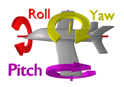
The five-axis system can bring the motion of two rotating axes into real-time measurement, and work with three linear axes to realize the effect of “measuring side-by-side motion†of the probe part. This gives greater flexibility than a three-axis system. With the advancement of industrial technology, five-axis processing equipment has begun to be widely applied to the processing of complex parts, but this trend has not been popularized in the measurement field. Most coordinate measuring machines still remain in the traditional three-axis or Four-axis technology level. The inequality between “five-axis machining†and “three-axis measurement†will inevitably bring certain difficulties to the measurement, resulting in a blind spot for measurement.
Another difference between the five-axis system and the three-axis system is the indexing of its rotating axis. The rotating axis of the three-axis system is only used to change the angle of the probe without participating in the measurement, so it has a certain angular division value; The linkage rotary axis of the shaft system participates in the measurement process, and the probe angle is continuously changed. In other words, the probe angle of the five-axis system is steplessly indexed. Let's imagine this situation: When preparing the measurement program, we configured and calibrated the required probe angle for the orientation of the part being tested. When the next part is placed on the workbench, but its orientation is inconsistent with the previous part, the previous probe angle may no longer apply. Therefore, when doing batch measurement, we have a certain degree of requirements for the position and attitude of the part. For the five-axis system, the requirements in this aspect will be much looser. The stepless indexing feature of the probe allows the probe to adjust according to the alignment of the part coordinate system, avoiding the situation where the probe angle is not applicable.
[Contact probe and optical probe]
In recent years, some misleading propaganda has been popular, which has led some users to have high expectations for optical probes, such as “sweeping with an optical probe, all the dimensions of the parts are outâ€, etc., which are optical probes. There is actually a big misunderstanding. From the current state of view, the contact and optical probes are mainly complementary, not competitive.
Where do the contact and optical probes complement each other? This also needs to start with the type of optical probe. Three-dimensional optical probes have different classifications, such as point source, line source, and surface source. Different probes have significant differences in their applications. We broadly divide the application of optical probes into two categories: surface digitization and three-dimensional measurement. Some people can't help but wonder: Is surface digitization and 3D measurement not the same thing? In fact, the key to distinguishing between two applications is whether to generate a Digital Surface Model, which is often referred to as a point cloud or a triangular grid. Of course, in many practical applications, the generated digital surface model will be used later for surface or feature element measurement, but this measurement mode is based on the digitized part model, which is fundamentally different from traditional direct measurement feature elements.
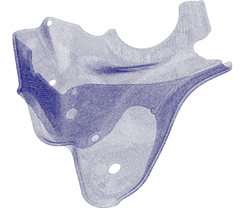
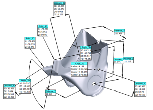
For surface digitization, the purpose is to obtain the surface contour of the part, which requires a large amount of spatial point coordinates of the contour. For the contact probe, the one-by-one acquisition method is not capable of meeting the requirements of millions of points. Even if the probe is continuously scanned, the speed of the point is increased only by the way the probe does not leave the surface of the part. In essence, it is still a single point of acquisition. In this type of application, the line source and the surface source probe make up for the shortcomings of the contact probe. The line scan probe can scan an area by moving a laser with several points on the surface of the workpiece; The probe is used to acquire a point cloud in a specific size area at a time through a set of coded ray grids.
After obtaining the digital surface model, the user can use the data for various purposes, such as comparison with the CAD model, to obtain the deviation of the overall/local contour of the part, three-dimensional size measurement or reverse engineering. However, when this measurement method is used for dimensional and behavioral tolerance measurement, it usually cannot meet the requirements of the measurement process flow (such as establishing measurement basis, selecting element fitting method, selecting evaluation reference, etc.). However, some parts may require non-contact measurement due to part specificity, such as soft materials, surfaces that are not allowed to touch, tiny features, etc., or for measurement efficiency requirements. For such applications, the point source probe also compensates for the lack of contact probes.
In fact, optical probes have another advantage over contact probes. When the contact probe picks a point, the probe records the space coordinate of the center of the ball, and then compensates according to the radius of the ball to obtain the coordinates of the actual point. However, when measuring the three-dimensional curve at a specific position, if the point is not taken according to the normal direction of the measuring point, there will be a radius compensation cosine error; if the point is taken according to the normal direction of the measuring point, the actual measuring point position will be generated. A deviation occurs. This situation is especially common when measuring turbine blades.
The non-contact optical probe directly uses the reflected signal of the light spot to acquire the coordinates of the measured point, and there is no radius compensation link, so the source of the cosine error can be completely eliminated. Furthermore, when measuring variability parts, although the force is not large, the parts will cause some deformation under the action of force (such as the thin blade in the figure below. When measuring the top section, the blade is affected by the force measurement during the basin. Bend toward the back of the leaf, and vice versa). Although the amount of bending deformation is not large, considering the extremely thin blade itself, the relative deformation amount is still very considerable, which has a very large influence on the obtained contour and position.

In addition to the spot probe, the surface light source camera can also have 3D measurement capability, but the camera probe is not based on the acquired point cloud when used as a 3D measurement, but directly depends on the captured 3D image. Extract the measured elements. Moreover, when the camera-type probe is used for three-dimensional measurement, it is not used alone, but with the contact probe, the contact probe is responsible for establishing the measurement reference, while the camera-type probe is for some special element features (for example Holes, grooves, etc.) are measured.
Although optical probes have some advantages that contact probes cannot provide, they do not completely replace contact probes because the accessibility of light is not as good as that of contact probes. Each part of the ball can touch the object to be measured, but the light travels along a straight line. We can't let the light "turn". There must be some features that make the light impossible. For example, the depth-to-depth ratio is small. Contact holes are more convenient than optical probes in the case of holes or L-shaped styli.
[Conclusion]
There is no best probe, and there is no omnipotent probe. The final choice depends on the measurement needs. In the face of a variety of complex probe types, not budget-oriented, not seeking a versatile probe, in order to find a truly suitable product, quality control is fast and good.
references
1 Zhao Qiancheng Deng Shanxi Ding Xing, Determination of Measurement Points in Roundness Measurement, Journal of Agricultural Machinery, January 2004, Vol. 35, No.1
A Workstation sink is a sink with a mechanism built in to the front and back sides of the bowl to allow accessories to sit on the step or ledge, affording the user to prepare meals on the sink instead of on the countertop. The intent behind the design is to speed up the process of food preparation and clean-up.
Workstation Sink,Farmhouse Workstation Sink,Work Station Kitchen Sink,Workstation Farmhouse Sink
JIANGMEN MEIAO KITCHEN AND BATH CO.,LTD , https://www.jmmeiaogroup.com