The center of gravity of the horizontal milling and boring machine or the machining center's headstock often changes. This change of center of gravity will affect the accuracy of the machine tool, which directly affects the precision of the workpiece. To solve this problem, a design of the center of gravity compensation system is proposed. Program. The compensation scheme only reduces the accuracy caused by the tilt of the headstock after the change of the center of gravity, and cannot compensate for the decrease in precision caused by the downward deflection of the spindle due to wear and insufficient rigidity.
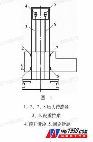
Horizontal milling and boring machine When the spindle moves along the W axis or when the front end of the spindle is attached, the headstock will be bowed due to the change of the center of gravity. This heading phenomenon occurs because of the necessary movement gap between the headstock and the column guide. This kind of gap cannot be eliminated, so this kind of bow is inevitable. Although some machine tools have been designed with this in mind, it is more advantageous to use a double counterweight cable to balance the single cable pair. However, due to the elastic deformation of the cable, etc., the position of the headstock will always change with the change of the center of gravity. At this time, if the change can be detected in time and corrected at any time, the dynamic compensation of the accuracy can be realized. The design idea is: the four head pressure sensors 1, 2, 7, 8 detect the head of the headstock, control the servo motor, and then lift the pulley 4 after the gear is decelerated, so that the headstock can be raised to achieve the purpose of compensation. (see picture 1).

1. Measurement principle and system composition
(1) Detection method: The change of the position of the center of gravity will inevitably cause the tilt of the headstock. How to detect such a slight tilt can be done in a variety of ways: 1 direct detection, using displacement sensors, grating scales, etc. 2 Indirect detection, the slight displacement of the headstock will change the pressure at the four points of 1, 2, 7, and 8. In a certain range, this pressure change is proportional to the tilt of the headstock. Therefore, the test can be used. The amount of change of the pressure value at 4, 7, and 8 points indirectly detects the amount of tilt of the headstock; comparing the two detection methods, direct detection requires a certain amount of displacement, and the structure is complicated by grating scales, and the environment is high. The method of indirectly detecting the pressure change requires almost no displacement, and has a simple structure, high sensitivity, and low environmental requirements. Therefore, the indirect detection method is adopted in the present scheme.
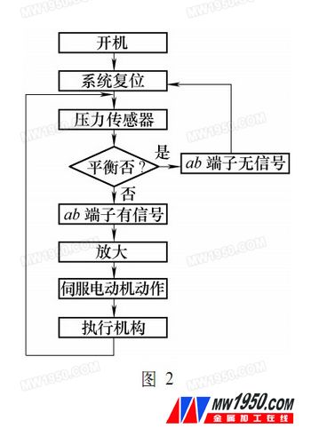
(2) System composition: The compensation system consists of an electric part and a mechanical part. The electric part consists of four pressure sensors and signal amplifiers connected in the form of a Wheatstone bridge. The power amplifier and the servo motor form an execution circuit. The mechanical part consists of the deceleration mechanism and the jacking pulley, and the entire compensation system flow chart (see Figure 2).

Pneumatic Valve,Control Valve,Steam Valve,Fully Welded Ball Valve
ZHEJIANG KINKO FLUID EQUIPMENT CO.,LTD , https://www.kinkoflow.com