The cylinder head is an important part of the internal combustion engine, and its machining accuracy directly affects the working performance of the engine. When the engine is working, since the combustible gas is ignited after being compressed in the cylinder head combustion chamber, the valve seat is subjected to high heat load and mechanical load. This requires both the valve seat to have high wear resistance and a good seal. If the center of the valve stem is offset, it will cause harmful heat conduction and rapid wear of the valve stem and the conduit hole, and will also increase the fuel consumption. Therefore, high requirements are placed on the machining accuracy of the valve seat and the conduit hole, and in particular, the tightness of the coaxiality between the working cone surface of the valve seat and the conduit hole is set.
For gasoline engines, the concentricity tolerance is specified as 0.015-0.025 mm, while for diesel engines it is only 0.01-0.015 mm (in the combustion chamber, the compression ratio of diesel combustible gas is 2-2.5 times larger than that of gasoline). In high-volume production, in order to maintain such tolerances in a stable manner, in addition to the need to optimize the machining process, the selection of the positioning reference, the reasonable structure of the special tool and the fine boring head and its accuracy are of great significance.
The machining of valve seats and conduit bores is a key technology for cylinder head machining. For a long time, many combination machine tools and tool manufacturers at home and abroad, such as Dalian Machine Tool Research Institute, Ex-Cell-O, Alfing, Grob, Hüler Hille, Ernst Krause & Co, and other tool factories and Komet, Plansee, Beck, Mapal and other tools. The factory attaches great importance to the development of such technical equipment and special tools. In recent years, great progress has been made, especially in the development of special tools, which has a positive effect on improving machining accuracy, tool durability and machining efficiency.
Bottom hole machining of valve seat and conduit hole
The accuracy of the bottom hole of the valve seat and the conduit hole is an important factor that directly affects the final machining accuracy of the valve seat and the conduit hole. Because the coaxiality error of the bottom hole (generally lower than 0.02-0.05mm) will result in uneven distribution of the valve seat and the conduit hole finishing allowance, thus affecting the final machining accuracy.
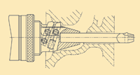
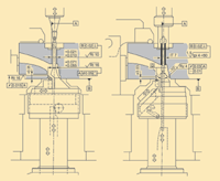
In order to ensure the coaxiality tolerance of the valve seat and the bottom hole of the conduit hole, many manufacturers use special composite tools, and drill, expand, semi-finish, and finely process three processes. In order to enhance the rigidity of the slender mast, most of them use a carbide mast (Fig. 1), but also use a back guide support (Fig. 2). Since the elastic modulus of cemented carbide (E=500000N/mm2-630000N/mm2) is about 3 times larger than steel (E=20000N/mm2), the mast made of cemented carbide can obtain better rigidity ( R=3EI/L3). The back guide support method can also enhance the rigidity of the mast, but in order to ensure the support effect, the back guide support sleeve and the center of the mast should maintain a sufficiently high coaxiality, and the structure is also complicated.

Figure 1: Special tool with carbide mast 
Figure 2: Fine valve seat and conduit hole (left), finishing valve seat working cone and conduit hole (right)
Cylinder head positioning
When finishing the working valve face and the conduit hole of the valve seat, most of them are positioned by the joint surface with the cylinder and the two positioning pin holes on the plane. This type of positioning, which has been commonly used, is caused by the positional error between the clamp locating pin and the valve seat, the conduit hole, and the positional error between the adjacent valve seat (and the adjacent conduit hole). The offset of the margin, in the final finishing, causes the reamer with poor rigidity to also cause machining offset, so the positioning method is not always able to achieve the specified accuracy.
Therefore, in order to ensure the processing accuracy, it is necessary to reduce the positioning error to improve the uniformity of the machining allowance. Otherwise, it is reasonable to process the valve seat and the conduit hole twice.
The cylinder head is positioned by the outer circumference of the plane and the conduit hole, which can significantly reduce the above positioning error (Fig. 2 right). With this positioning method, the positioning guide sleeve of the clamp should be kept strictly coaxial with the machine tool spindle to ensure uniform distribution of machining allowance. In this way, the valve seat and the conduit bore can be machined to the specified tolerances. However, the disadvantage is that only one seat and conduit hole can be machined in one station. Compared with the positioning method of one pin and two pins, the productivity is lower, that is, in the case of maintaining the same productivity, a certain number of processing stations need to be added, thereby increasing the length of the production line.
Special tool for machining valve seats and conduit holes
Simultaneous machining of the valve seat and conduit bore with a dedicated tool facilitates increased concentricity. The working cone of the machining valve seat is generally formed by two processes of boring and turning. The angle of inclination of the boring blade is equal to the half cone angle of the working cone of the valve seat. When machining, because the valve seat is hardened material (HRC50-58), the cutting edge wears faster, and the contour of the blade wear will be copied on the sealing cone surface, thus affecting the sealing performance of the valve seat. However, the advantage is that the structure of the tool and the control of the cutting motion of the tool are relatively simple, and the processing efficiency is also high.
The working cone of the seat is machined by the turning process to avoid defects during boring. When machining the valve seat, it is generally necessary to machine the end face of the valve seat, the 75° cone and the 45° working cone. The first two faces are machined to obtain a working cone with a constant width. Figure 4 is a special tool for machining the valve seat and the conduit hole. The slide tool holder inclined on the special tool is used to machine the working cone of the valve seat, and the three fixed tools are used to machine the end surface of the valve seat. ° and 75° cone. The reamer for machining the conduit hole is guided by a guide sleeve mounted at the end face of the special tool. In order to ensure the coaxiality between the guide sleeve and the machine tool spindle, the guide sleeve can be ground after the guide sleeve is inserted into the cutter body to eliminate the manufacturing error and assembly error of the component. The guide rail of the special tool body is precisely manufactured according to the angle of the working cone of the valve seat, so the machining accuracy and repeatability of the working cone surface can be guaranteed.
Before the start of machining, the two push rods that respectively push the slide and the reamer are in the starting position, so that both the turning tool and the reamer are in the initial position of the machining (the reamer only extends a few millimeters out of the guide sleeve). At the beginning of the machining, the fixed-mounted tool first slams the seat and end face (blade II) and chamfers (blade III and IV) (Fig. 3). Then the cutters are retracted by about 0.2 mm, so that the cutting edges II, III and IV are separated from the working surface, and the turning tool mounted on the inclined sliding plate is in the position to be processed. At this time, the sliding plate is pushed by pushing the outer push rod to the valve. The working cone is used for finishing the car. After the machining is finished, when the slide plate is moved to the end position, the rotation speed of the special tool is adjusted according to the reaming speed, and the inner push rod pushes the reamer to realize the reaming of the pipe hole. When the reaming is finished, the push rod is retracted and the tool is retracted to the starting position.
If the CBN tool is used to turn the working cone of the valve seat, the centrifugal force generated during machining will affect the machining accuracy due to the high speed (2000r/min-3600r/min). Therefore, balance should be adopted for this special tool. skateboard.

Figure 3: Processing of the valve cone working cone 
Figure 4: Tool for machining valve seats and conduit holes
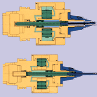
As high-speed machining centers enter the automotive industry, more and more cylinder heads have turned to machining centers for machining. Since the machining center is difficult to provide a cylinder for pushing the reamer at the rear end of the spindle, only other methods can be sought. Mapal and Beck have developed special tools for machining centers that use centrifugal force control (Figure 5). When the tool is machining the valve seat and the conduit hole, the tool first boring the valve seat taper at 1000r/min. After the machining, the tool retreats by about 0.2mm, and then the tool speed is increased to 5000r/min. The generated centrifugal force is radially outwardly displaced, squeezing the oil in the oil chamber, and the reamer is used to machine the conduit hole at a constant feed rate by means of valve control. When the conduit hole is finished, the speed of the special tool is reduced to 1000r/min, and the reamer automatically retracts to the starting position.
Reamer
The tools used to machine the conduit holes are either single-edged or multi-edge reamer. Since the single-blade reamer relies on two guide bars arranged on the cutter body to guide and support the cutting force during the reaming process, it is less sensitive to the unevenness of the machining allowance, which is advantageous for improving the valve valve. The coaxiality of the working cone and the processing of the conduit hole.
With a multi-blade reamer, the processing time of the conduit hole is generally reduced by about 75% compared to a single blade due to the higher feed rate. However, this reamer is sensitive to uneven machining allowance and affects the valve. The coaxiality of the working cone and the processing of the conduit hole. At present, the single-edge reamer is used to ensure the machining accuracy from the level of machining technology on the automatic line of the combined machine tool.

Figure 5: Special tool for propelling the feed with centrifugal force

Figure 6: Comprehensive accuracy measurement of valve seat and conduit bore
Spindle component
As a rule of thumb, the machining accuracy of the valve seat and the conduit bore is largely related to the rigidity and accuracy of the spindle component. Therefore, the radial runout of the spindle component should be less than 2 mm and the end face runout should be no more than 1.5 mm. The magnitude of these deviations directly determines the roundness of the working cone of the valve seat, which affects the sealing of the valve seat during operation.
Most of the main shaft components use triple (or double) angular contact ball bearings as the front bearings, and double-joint angular contact ball bearings are used as the rear bearings. The accuracy grade of the bearings is generally P4.
Automatic detection of valve seat and conduit hole machining accuracy
The quality of the cylinder head is monitored on the automatic line, usually with a measuring station behind the finishing station. Figure 6 shows the automatic measuring device for the comprehensive accuracy of the cylinder head valve seat and the conduit hole. The unit uses four pneumatic measuring heads to simultaneously measure four seats and conduit holes. An annular nozzle having a slit width of about 50 mm is provided on the measuring head of the working cone of the measuring seat, and the measuring rod of the measuring tube hole is also provided with a measuring nozzle. When the mandrel is introduced into the conduit hole at a low speed, the working cone of the valve seat is automatically centered and aligned, which is achieved by specially designed rolling bearings. And by means of the spring, a certain bonding force is applied to the measuring head for measuring the roundness of the working cone of the valve seat, so that the measuring head rests on the working cone surface. When the compressed air is turned on for measurement, it can be determined by the amount of gas discharged from the annular nozzle:
- The roundness of the working cone of the valve seat
- Roundness of the conduit hole
- The running error of the valve seat working cone facing the conduit hole
Conclusion
From the analysis of various processing techniques for valve seats and conduit holes, the following ways to improve the machining accuracy can be proposed:
- In order to improve the coaxiality of the working cone of the valve seat and the conduit hole, the uniform processing allowance of the conduit hole should be ensured, which can be achieved by positioning the cylinder joint surface and the outer circumference of the conduit.
- The working cone of the seat is machined to avoid some of the defects in the boring process.
- The use of a single-edged reamer in the final machining conduit hole is advantageous in overcoming machining errors caused by machining allowance offset.
- When using a high-speed turning seat working cone, a special tool with a balanced slide is used.
- The axial and radial runout of the spindle components should be less than 0.0015 mm and 0.002 mm, respectively.
With the continuous development and popularization of tool materials and special tools, especially the development and improvement of special tools suitable for machining centers, the machining accuracy, machining efficiency and processing flexibility of valve seats and conduit holes will be further improved.
Loose Hex Key,Hex Allen Wrench,Allen Key Bit Set,Security Allen Wrench
henan horn tools co.,ltd. , https://www.nbhorntoolsltd.com