Programmable Logic Controller (PLC), which has the advantages of high reliability and strong anti-interference ability, is widely used in industrial control and has become one of the main pillars of modern industrial automation. In the design of the PLC control system, I/O point resources are often encountered and the price/performance ratio is contradictory. Some controlled devices need to have manual and automatic working modes, and there are many manual partial control buttons. In some automatic production lines, the position switch for position detection or the output for system working status indication is more, which will make the occupied I/. The O point is greatly increased. Generally, it is solved by adding an expansion module, but the PLC I/O point is expensive, and there are limits on the number of expansion modules and the number of I/O points. For example, the number of maximum expansion modules of the CPU 226 of SIEMENS is 7, and the maximum expansion is 168 digital quantities. I/O point or 35 analog I/O points. If you increase the CPU at this time, it will inevitably reduce the cost performance of the system. In this case, expanding the number of I/O points has great practical significance. This article takes SIEMENS S7-200 PLC as an example to explore how to extend the I/O points in the PLC control system.
2, hardware circuit I / O point expansion method
2.1 Time-sharing group input
For PLC working modes that have both manual mode and automatic mode, and the two cannot be executed at the same time, the input of different working modes can share the input point of one PLC. The time-sharing group input expansion I/O points wiring diagram is shown in Figure 1. I1.0 is used to input automatic/manual command signals for automatic and manual program switching; diodes are used to cut off parasitic circuits and avoid false signals; SA is used to switch between automatic and manual operation.
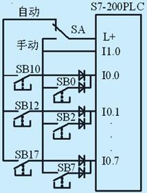
Figure 1 Time-sharing group input wiring diagram
2.2 shared output contact
For the load with the same on-off state, if the output point power allows, it can be connected in parallel to the same output point, that is, use one output point to drive multiple loads. Special attention must be paid to exceed the allowable load of each output point. ability. The wiring method is shown in Figure 2.
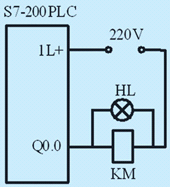
Figure 2 Common output point wiring diagram
2.3 Merging input contacts
For a control request for multi-point starting and stopping of the motor realized by the button and the contactor as shown in FIG. 3, for example, starting and stopping can be realized in three places, wherein SB1, SB2, SB3 are start buttons, SB11, SB12, SB13 is the stop button. Each button can be connected to an input point of the PLC, which is easy to implement. If the input point of the PLC is relatively tight, it can be wired in the way shown in Figure 4. Compared with the way each button occupies one input point, the software programming of the method is simpler.
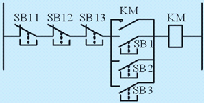
Figure 3 Motor electrical control schematic
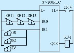
Figure 4 Motor PLC control wiring diagram
3, software programming I / O point expansion method
The basic idea of ​​software extension is dual-use or round-robin multiplexing. That is, when the button is first pressed, the output request is high; when the button is pressed again, the output request is low; when pressed again, it is high, and so on. This saves an input point and saves more input points when the system has more switching control. For example, the host ON and the host OFF, the paper holder and the paper holder can be controlled with only one input point. . There are many programming methods to achieve "one point and two use", such as the use of internal auxiliary relays, timers, counters, shift instructions, etc. This article only introduces several simple methods.
3.1 Using edge detection, output instructions
If the button SB is connected to I0.0, the output control Q0.0 is realized by the edge detection and output command, and the STL program compiled with STEP7 V5.3 is as follows.
A I0.0
FP M0.0
= M0.1
A M0.1
A Q0.0
= M0.2
A (
O M0.1
O Q0.0
)
AN M0.2
= Q0.0
Program Description: When the button SB is pressed for the first time, the normally open contact of I0.0 is closed. Under the action of the RLO edge detection command FP, the auxiliary relay M0.1 is turned on for one scan cycle, thereby outputting the relay Q0.0. The coil is energized, and Q0.0 constitutes a self-locking (holding) circuit, while the other pair of normally open contacts of Q0.0 are closed, ready for M0.2 to be turned on; when the button SB is pressed for the second time, Under the action of the FP command, the normally open contact of M0.1 is connected to the coil circuit of M0.2, and the normally closed contact of M0.2 cuts off the output of the PLC, thereby achieving dual use.
3.2 Using edge detection, jump instructions
If edge detection and jump instructions are used, it is easier to implement, and the STL procedure is as follows.
A I0.0
FP M0.0
JNB OUT
AN Q0.0
= Q0.0
OUT: NOP0
Program Description: The function of the 4th and 5th statements is to realize the self-reversal of Q0.0, but if there is no previous jump instruction, the program will invert the state of Q0.0 once every scan cycle; The role of the two sentences is to limit the inversion of the I0.0 only when it is up, otherwise it will jump out of the inversion block, thus achieving a little dual use.
3.3 Using edge detection, XOR instructions
If it is easier to implement with edge detection and XOR instructions, the program is as follows.
A I 0.0
FP M0.0
X Q0.0
= Q0.0
Program Description: When the rising edge of I0.0 is detected for the first time, Q0.0 is 0 at this time, so the output Q0.0 is 1 after XOR. When the second scan cycle comes, it is not the rise of I0.0. It is 0, but Q0.0 is indeed 1, so the result is still 1 after XOR; when the 2nd edge is detected, Q0.0 is 1, and X0 is output after XOR The result is 0. Wait until the next scan cycle is reached, it is not a rising edge, and Q0.0 is still 0, so the XOR keeps the output still at 0.
4, hardware and software combined with I / O point expansion method
4.1 Hardware coding and software decoding, extending the input point
In the case of a large number of input signals of the control system, the encoder can be used to encode the input signal, and then input to the input end of the PLC, and then decoded by the internal program of the PLC to identify each input signal, which can greatly reduce the input. The occupation of the point. The external wiring of the PLC is shown in Figure 5. Since the ordinary encoder will have garbled characters when multiple signals are input at the same time, the 8-line-3 line priority encoder 74LS148 can be used to set the priority of the signal, and sometimes the strobe output and expansion of the encoder are also required. The terminal is also connected to the PLC, and the program is used to reduce misjudgment. In addition, it is also necessary to pay attention to the level matching problem (between +5V of the signal circuit and +24V of the PLC) and the technical specifications required for the signal recognition of the input port of the PLC (the range in which the drive current and voltage can be recognized), and sometimes Appropriate signal amplification and isolation circuits need to be added.
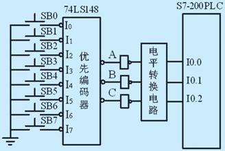
Figure 5 hardware code wiring diagram
The following uses the button SB2 as an example to illustrate the program identification method for PLC internal software decoding. According to the function table of 74LS148, the chip is active low, so the output level of three non-gates is converted into positive logic in Figure 5. If SB2 is pressed, no matter whether SB0 or ​​SB1 is pressed, but SB3~SB7 are not pressed; at this time, the output of ABC is 101, and the states of I0.0, I0.1, and I0.2 after the non-gate are respectively 0,1,0; The corresponding STL decoding procedure is as follows.
LDN I0.0
A I0.1
AN I0.2
= M0.2
In this way, the author replaces the button SB2 with the normally open contact of M0.2 in the program. That is, when the button SB2 is pressed, M0.2 is 1; SB2 is bounced, and M0.2 is 0 again, thereby realizing the function of software decoding. In addition, it should be pointed out that the method can only read one of the eight input states in each scan cycle of the PLC. If more than two switches are closed, the PLC can only detect the signal with the highest priority.
4.2 Software coding and hardware decoding, extending the output point
In the case that the control system has a large number of output signals, the output signal can be encoded by the internal program of the PLC, and then decoded by the hardware decoder to drive the load, which can greatly reduce the occupation of the output point. The external wiring of the PLC is shown in Figure 6, using a 3-wire-8-line decoder 74LS138. At this time, there is also a problem of level matching, that is, the typical output of the DC module of the PLC is +24V, and the operating voltage of the signal circuit is generally +5V. Therefore, it is sometimes necessary to increase the signal circuit and the power amplifying circuit to drive the load.
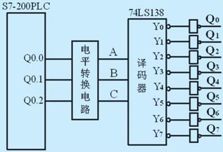
Figure 6 PLC wiring diagram
The following describes how to make Q2 1 as an example to illustrate the encoding method of PLC internal software. According to the function table of 74LS138, if the output Q2 is to be 1, the output of Y2 should be 0; that is, the corresponding ABC should be 010, so that the Q0.0, Q0.1, and Q0.2 of the PLC are respectively 0. 1,0 can be; the corresponding STL encoding procedure is as follows, where M1.2 is the condition for setting output Q2.
LD M1.2
S Q0.0, 1
R Q0.1, 1
S Q0.2, 1
In this way, it is only necessary to combine Q0.0, Q0.1, and Q0.2 to set the outputs Q0 to Q7 to 1. There is an obvious disadvantage in this method, that is, only one of eight states can be outputted per scan cycle, and it is not possible to simultaneously set the outputs Q0 and Q1.
4.3 Identifying N × (N + 1) / 2 input signals with N input points
If we connect the input signal to the form of Figure 7, we can use 3 input points to identify 3 × (3 + 1) / 2 = 6 input signals with software programming. The basic idea is: When SB1 is pressed, the PLC only detects that I0.0 is "1". At this time, the states of I0.1 and I0.2 are both "0", then I0.0 will be in the program. The normally open contact and the normally closed contact of I0.1 and I0.2 are used to identify the state of SB1; if SB2 is pressed, both I0.0 and I0.1 are "1" and I0.2 is "0". "At this time, the identification program should be the normally open contact of I0.0 and I0.1 and the normally closed contact of the upper I0.2; similar to the case of other points, the STL identification procedures of the input signals SB1 and SB2 are as follows, wherein The states of M2.1 and M2.2 represent the states of signals SB1 and SB2.
LD I0.0
AN I0.1
AN I0.2
= M2.1 // Identification of signal SB1 LDN I0.0
A I0.1
A I0.2
= M2.2 // Identification of signal SB2
It should be pointed out that this method cannot recognize that two or more signals are simultaneously 1 at the same time. If SB1 and SB3 are simultaneously turned on, the program will recognize it as if SB2 is turned on. The role of the diode in Figure 7 is to isolate the parasitic current to form a path. In fact, you can use up to 7 signals to identify with 3 input points. If you add another SB7 in Figure 7, and connect 3 diodes to I0.0, I0.1, and I0.2, you can pass 3 The normally open contact of the point is used to identify the SB7, but this is too cumbersome and therefore generally not used.
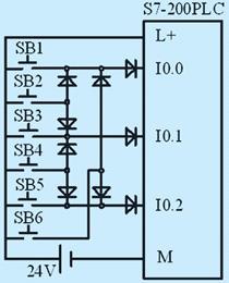
Figure 7 hardware wiring diagram
4.4 Forming a matrix keyboard with input/output ports
If the control system needs to design a keyboard, the conventional idea is to connect each button to an input port. However, when the number of keys is increased, the input point is extremely wasted. Therefore, imitating the idea of ​​making a matrix keyboard in the microcomputer system, the I/O points are used to form a matrix keyboard in the PLC system, as shown in Fig. 8 is a 3×3 keyboard structure. Figure. Programming ideas: First, determine whether there is a key press on the entire keyboard. The method is to output all the lines to 1, and then read the status of the column. If the status of the column read is all 0, no key is pressed, not all 0. Then there is a key press; secondly, scan by column, the method is to send the row line 1 in turn, check the status of the corresponding column line, if the column line is all 0, the button is not in this line; if not all 0, the button must be This line is the one that intersects the 1-level column line. It can be seen that the corresponding software programming is more complicated, but in some small control systems, the operation screen or the touch screen can be avoided, thereby improving the system cost performance. Contact the author if you need a detailed hardware design and software program.
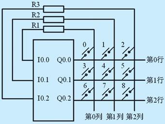
Figure 8 3 × 3 keyboard structure
5, the conclusion
This paper discusses the method of extending PLC I/O points from three aspects: hardware design, software programming and hardware and software combination. In the specific application, it is also necessary to consider some advantages and disadvantages of each expansion method and anti-interference ability. If these methods can be used reasonably, it will effectively save the PLC's I/O points, reduce the system cost, provide cost performance, and fully utilize the advantages of PLC.
Furniture Casters,Hand Cart Caster,Trolley Wheel Caster,Hand Cart Swivel Caster
JIANGSU SHENPAI CASTER CO., LTD , https://www.shenpaicaster.com