With the rapid development of the automotive industry, in order to meet the requirements of safety, environmental protection, energy conservation and other indicators, the application of laser welding technology in the field of body-in-white manufacturing is becoming more and more popular. In the white body laser welding process, the white body accuracy, matching relationship and equipment accuracy error and other factors cause the welding environment to be more complicated, the welding path and the original setting program are prone to deviation. To solve this problem, the current three-dimensional visual tracking system It has been widely used in laser welding systems to perform the function of detecting and correcting at any time during the welding process.
1. Application background of laser welding technology on a light passenger car of Jianghuai Automobile
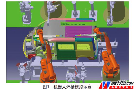
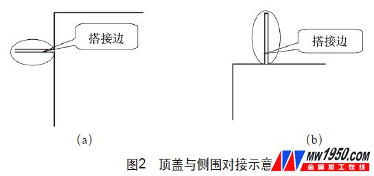
In 2011, Jianghuai Automobile intends to develop a short-shaft model with a blind window shape (that is, all the side window frames are partially closed) based on the original long-axis new models. According to the above changes, the feasibility analysis of the welding process is carried out. If the traditional spot welding process is adopted, the robot welding torch must protrude from the front windshield and the rear door frame into the interior of the vehicle body (see Figure 1), and the throat depth of the robot welding torch must be reached. 2.5m, and at the current level of welding gun manufacturing, this requirement cannot be achieved. Therefore, it is not feasible to connect the roof and side wall of the body by the traditional spot welding process; in this case, consider changing the overlapping form of the roof cover. Docking form (see Figure 2), but this structure requires additional exterior strips to shield the solder joints. The overall shape of the body is not beautiful. At the same time, it will also cause problems that the company's series models cannot be extended. Based on this, through the investigation of laser welding technology, it was finally confirmed that robot laser welding technology was used to solve this problem.


2. Brief introduction of the composition and equipment of short-axis light passenger car laser welding system
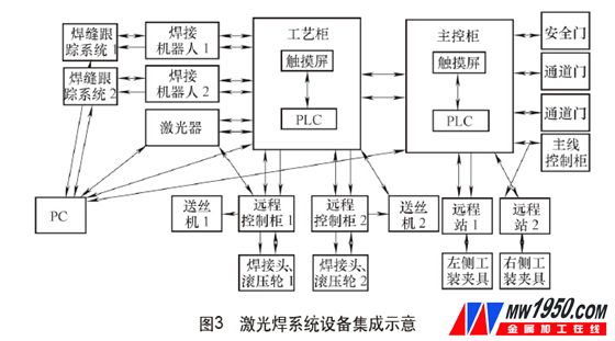
In response to the characteristics of this model of our company, a complete set of laser welding system solutions was finalized, including welding system, dust removal system, tracking system and safety protection system, and the system was established through PLC system programming, as shown in Figure 3. Show.
Based on the characteristics of the laser welding process, research was carried out on the selection and selection of system equipment. Finally, suitable equipment was selected in each system. The basic equipment list of the laser welding system is shown in the attached table.


Based on the previous scheme demonstration and overall scheme design, the system equipment selection is basically as follows: IPG4000W fiber single laser dual optical path time-sharing output system, welding head selects weldingsonic welding head specially used for laser filler welding, Fonnis pushes back and pulls The wire feeder, 6-axis robot is subjected to load calculation and off-line simulation. The KUKAKR210 welding robot with 210kg load capacity and 2700m working distance is controlled by profibus.
The main functions and performance of each device are briefly introduced as follows:
(1) Laser generator This system uses IPGYLS-4000 high-power fiber laser to produce laser with a wavelength of 1070 nm. The laser generated by the laser module is transmitted from the feeding fiber to the beam coupler, and the beam output from the feeding fiber is coupled into the processing fiber through the beam coupler. The processing fiber is 30 m long, which can meet the long-distance welding. The fiber output spot diameter is 0.6 mm. The laser uses a built-in water cooling system and contains two cooling waters: the tap water cools the laser module, the temperature is controlled between 20~22 °C, the deionized water cools the internal fiber coupling module and the external optical path, and the temperature is controlled between 28~30 °C. Fiber optic lasers have an electro-optic conversion efficiency of up to 28%, while lamp-pumped YAG lasers are only 1.5% to 2%, eliminating the need for lamp replacement and saving money. Fiber-optic lasers use carrier-grade single-core junction semiconductor laser tubes with a lifetime of up to 100,000 h. The spot size and shape of all power stages are fixed, maintenance-free or low-maintenance, and there are few spare parts. For flexible processing, suitable for longer working distances.
The laser contains two optical paths, and the optical path is switched by time sharing. The power of the laser is 4000W, which can be used for cutting and welding, and high-speed control. Normal high-power operation consumes about 14kW/h. The laser cooling system requires high ambient temperature and requires the ambient temperature of the air-conditioned room to prevent the cooling water from freezing. There is also a high requirement for the use of optical fibers, and the bending radius is ≥150 mm when dynamic.
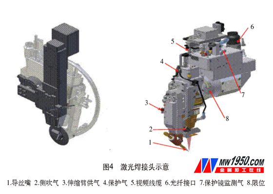
(2) Laser welding head This system adopts SCANSONICAL02 laser wire welding and welding joint (see Figure 4). The fiber is coupled from the fiber interface at the top of the welding head. After the laser beam passes through the working fiber from the laser generator to the laser welding head, it passes through. The collimating lens group is collimated, and then passes through the two reflecting lenses, and then reaches the focusing lens for focusing to become a laser spot for welding.

The welding head is provided with a camera module for observing and monitoring the relative position of the welding wire and the focused spot. There are replaceable protective lenses to prevent splashing or dust from entering the optical path system during soldering. The two layers of safety glass are filled with a certain pressure of detection gas. When the lens is damaged, the air pressure is not enough, and an alarm will be given. The telescopic arm also has a supply of air. If the pressure is not enough, the welding head controller cannot be ready. The welding head is equipped with side blowing and flow monitoring to monitor the flow of the side blowing gas to ensure stable welding quality.
The welding head is equipped with an adaptive rolling wheel unit, the rolling wheel type ADR-400, and the pressure of the rolling wheel is adjustable, which can meet the control of the weld gap under different rigidity of different welding sections.
The welding head has a wire-guided weld seam tracking system. There are three working modes: preparation, tracking, and maintenance, the equipment is powered on, the welding head is automatically returned to zero, and the welding head is in the preparation mode. When returning to zero, there is no interference in the swing range of the swing arm. After the wire is automatically tracked in place, it is tracked with a certain force.
(3) Weld seam correction system In order to ensure the repeated positioning accuracy of the vehicle body, it is necessary to carry out the body weld seam positioning test for each car to ensure the consistency of the weld seam position. On the weld, the design selects four datum points to define the exact position of the current weld based on the standard body and datum offset (see Figure 5).
Weld seam correction using the server-robot laser scan tracker. By scanning the weld seam, the system obtains the deviation value of the weld seam from the standard vehicle body, communicates with the robot, and corrects the robot trajectory, so that the welding system can better adapt to the error of the vehicle body.
The specific work process is shown in Figure 6. In the first step, the calibration point is opened and the track point is required to be near the start of the weld. From the oblique front to the weld. At this point, the rolling wheel is at the upper limit, the welding head is in tactilesearchmode, the laser is ready; the second step is to open the program number, requiring the welding wire to be 3~5mm away from the weld, and the telescopic arm is compressed to near 0. At this time, under the rolling wheel Pressure, the welding head is in seamtrackingmode, the laser is ready; the third step is the light soldering point. It is required to be more than 3mm away from the first point, the telescopic arm is compressed to near 0, the rolling wheel is in the down state, and the welding head is in the seamtracking mode.


3. Implementation effect
(1) System quality The laser welding system of our company has been running stably since the production in 2012. The overall welding quality is up to standard. After the strength, metallographic and sealing test, the quality of all aspects is up to standard.
(2) Economic Benefits Since the operation of the system, nearly 10,000 white bodies have been produced, and good economic benefits have been achieved. At the same time, automatic welding has been realized, and the on-site employees have been freed from heavy manual labor.
(3) Social Benefits 1 Introduce the first set of body-in-white laser welding system of independent car enterprises and realize the successful application, which has set a precedent for the industry and promoted the development of high-tech in the province, which is worthy of reference by peer companies. 2 Solved the problem that the multi-functional commercial vehicle top cover-side wall connection of our company is difficult, ensuring the smooth development of new models and solving the problem of serialization of new models. 3 laser welding technology has the advantages of high strength, good appearance quality and good sealing performance, which enhances the performance of our company's products.
4. Conclusion
Through the application of laser welding technology on our multi-functional models, the welding quality of our company's multi-functional commercial vehicle body-in-white has been greatly improved in strength, appearance and sealing, which has enhanced our company's product image.
Laser welding technology has become the trend of mainstream automobile manufacturers. Through the application of this technology, our company has broken the barriers of foreign companies and joint ventures in this technology application. At the same time, through the on-site debugging work, it has accumulated rich technical experience. The popularization and promotion of this technology in the later stage laid a good foundation.
Auto Reel Springs,Spring For Retractable Cord Reels,Flat Coil Springs,Return Coil Springs
Ningbo Yunsheng Elastic Components Co.,Ltd , https://www.yunshengsprings.com