The annular groove of the injection molding machine tie rod is the key to the entire cohesive structure. The processing of the annular groove is a vital part of the production process of the tie rod. Designing a new type of cyclone cutting compound machine tool and special tool and applying it to the annular groove of the tie rod for processing can effectively solve the problem that the original annular groove processing has poor chip discharge, low production efficiency and safe production cannot be guaranteed.
At present, the two-plate injection molding machine has become the mainstream of the market due to its reasonable motion and dynamic characteristics, convenient mold adjustment, good mold clamping rigidity and precision, compact structure and small footprint. The mold adjustment action of the second board is completed by the cohesive structure, and the nut is replaced by the hug nut. Among them, the tie rod is the key part of the whole injection molding machine, and the mold-adjusting thread of the three-plate injection molding machine is improved to the entangled annular groove, and the processing of the annular groove is relatively critical in the entire production process of the tie rod.
The processing of the rod groove groove is generally carried out by the CNC car sheet cutter. This kind of processing has many problems such as poor chip discharge and low efficiency. In the current high-speed development of the industrial field, the production method with high efficiency, high quality and low labor is inevitable. Direction, based on this trend, this paper redesigned the general CNC lathe as a new type of cyclone cutting composite machine and designed a special tool. The problem was solved effectively by the application in the processing of the rod groove.
1. Current situation of annular groove processing
The tie rods need to machine equidistantly arranged annular grooves on the outer surface of the column, as shown in Figure 1.
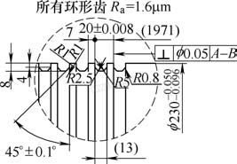
Figure 1 Pull rod outer circle machining annular groove
Single-knife cutting is about clamping the workpiece to an ordinary CNC lathe, and using a common slot cutter to perform CNC interpolation feed cutting on a CNC lathe. In the actual production process, the rough roughing of the car leads to the inability to break the chip, and the one-time feeding process forms a continuous strip of iron filings. In order to prevent iron filings from winding around the workpiece, entanglement of damaged tools and indiscriminate injury, it is necessary to equip the auxiliary personnel with long iron hooks for drawing, which poses a hidden danger for safe production; the knife blade is continuous in the slot cutter flute for a long time. Under the action of iron filings, the thickness of the thinning is reduced, resulting in a significant reduction in the life of the arbor; the iron filings generated by the slot cutter are covered above the slot cutter, causing the coolant to not fully enter the cutting point, and the high cutting temperature causes the tool wear to accelerate, and at the same time The machining accuracy is lowered and residual stress is generated on the machined surface.
2. Overall equipment modification design points
The current situation of the annular groove machining problem is analyzed, and a new machining method is designed to replace the original single-knife cutting. Through data comparison, the choice of cyclone milling and milling ring groove has the following advantages:
In high-speed machining, C-shaped short chips with good safety are formed, which takes away a lot of cutting heat to ensure tool life and reduce the heat transferred to the workpiece to help reduce the thermal deformation of the parts. As the cutting speed is increased, the cutting time and the cutting force are reduced, which is advantageous for the grooving of the poorly rigid parts while reducing the processing cost. From the perspective of CNC machining technology, NC programming of external cyclone milling is simple and the cutting accuracy is relatively high. After solving the problems of multi-tool cutting and high-speed cutting, combined with radial heavy-duty cutting and one-time clamping combined cutting, it is difficult to overcome.
Due to the need for a perfect outer circle, the original lathe tool holder must be retained. There is no standard radial heavy-duty cutting special cyclone cutting composite equipment in China, but the imported equipment is expensive, and the later use and maintenance costs are high. Based on the above analysis, the final solution was converted into a new cyclone cutting composite machine tool using the existing ordinary CNC lathe.
3. Structural features of the new cyclone cutting composite machine tool
Design a new type of special milling head for cyclone milling and cutter tool, and use it with the original equipment CKW61125 to solve the current problem of annular groove machining.
(1) Determine the processing principle of the whole machine tool. Figure 2 shows a new cyclone cutting composite machine. The working process drives the alloy coating forming blade for the rotation of the cutter head, and adopts high-speed cutting; the spindle of the lathe drives the workpiece to rotate slowly as the feed motion; the cyclone milling head is mounted on the lathe pallet and is driven by the carriage in the lathe. Motion acts as a radial feed motion.
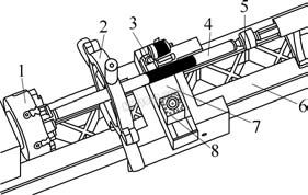
Figure 2 New cyclone cutting composite machine model
1. Machine chuck 2. Machine center frame
3. New special milling head for cyclone milling 4. Pull rod
5. Machine tailstock tip 6. Machine bed
7. Machine tool in the carriage 8. Machine tool holder
(2) The structure of the special milling head is shown in Figure 3. According to the actual situation of the processing rod annular groove, the feed direction is basically the X axis of the machine tool, mainly relying on radial cutting, so the radial cutting force of the main shaft of the special milling head is far greater than the axial force, therefore, the main shaft diameter The requirement for rigid load is relatively high, and the structural form of the relevant part of the special cyclone milling spindle supported by the annular groove of the tie rod is rationally designed, which plays a key role in realizing precision milling.
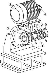
Figure 3 New special milling head model for cyclone milling
1. Center block 2. Cutter 3. AC motor (frequency control)
4. Motor pulley 5. Housing 6. Spindle pulley
7. Lubrication seal 8. Spindle bearing 9. Spindle
10. Special milling head (main part has base)
The optimized milling head structure of the optimized milling head is shown in Figure 4. After optimization, the front end of the main shaft adopts a tapered double row cylindrical roller bearing 3182114C, and the rear end is supported by a pair of tapered roller bearings 30309. The tapered roller bearing combination is mainly used to bear the radial and axial combined load mainly based on the radial load, so that the axial position of the main shaft is adjusted, and the axial clearance is adjusted, then the axial displacement of the shaft in the housing is restricted, greatly The overall radial load of the spindle structure is increased. Compared with angular contact ball bearings, the bearing capacity is greater, further ensuring the rigidity of the spindle structure. Therefore, the optimized design of the spindle structure is more compact, and it has better rigidity and precision when processing the groove of the drawbar, which can meet the requirements of cutting the annular groove milling.
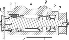
Figure 4 Special milling head spindle structure
1. Cutter 2, 7. Skeleton seal
3. Conical hole double row cylindrical roller bearing 3182 series
4. Spindle 5. Tapered roller metric 30000 series
6. O-ring
The spindle power is output by the motor. The traditional power transmission adopts the friction type belt-driven V-belt. Due to the alternating load during cutting, the belt will elongate and shorten, causing the cutterhead to generate circumferential vibration, resulting in the workpiece during machining. Damage to the tool and reduce the surface accuracy of the workpiece. The newly designed timing belt application form is that the belt and the teeth on the pulley are meshed and transmitted, the transmission is more stable, and the surface roughness value of the annular groove after processing is low.
(3) Cutter and cutter. The cyclone milling tool designed in this paper is designed according to the special contouring of the rod groove. The NX system is used to carry out accurate 3D solid modeling of the tool and performance analysis of the cyclone milling tool. Considering that each milling insert is interrupted, there is an impact force when contacting the workpiece. If the entire blade is shaped like a whole groove, the contact surface is too large, and the excessive load is added to the corresponding cutting in the form of distributed force. On the blade, a large amount of cutting heat is generated, which causes the tool to wear faster and the cutter head to vibrate.
How to reduce the cutting load is the key link in the design of the tool. Firstly, starting from the reduction of the contact surface, the entire blade is divided into two from the longitudinal direction, and the blade 1 and the blade 2 are alternately arranged on the circumferences of both sides of the cutter head, so that the load on each blade is reduced, and the whole is effectively improved. The service life of the group of tools and the feed rate are greatly improved, making high-speed cutting more reliable and reasonable. According to the above design requirements, the parameters recommended by the literature for the design and finite element structure analysis of the cyclone milling tool are selected. The rake angle of the blade is 0°, the back angle of the top edge is 8°, the back angle of the side blade is 4°, and the blade thickness is 4mm, the tool material is metal carbide hard alloy WC, the elastic modulus is 7.06e11Pa, and the bending strength is 1.7GPa. The surface is coated with a hard coating material.
The design of the cutter disc structure arranges a larger number of inserts to reduce the cutting load, and at the same time, the support portion of the lower part of the insert has to ensure sufficient strength. Then both analysis is carried out, and finally the design is to evenly arrange 18 blades, and the outer diameter of the cutter disc is 200 mm. Relying on the guide leveling key and the main shaft, the design speed is 0~2 000r/min, and the variable speed is realized by the AC motor (see Fig. 3) to realize the stepless speed change. The speed value is displayed on the control panel, and the touch screen is used for human-machine dialogue. The control is precise and simple.
4. Production application prospects
This new type of cyclone cutting composite machine designed according to the groove of the tie rod is equipped with a special milling head for cyclone milling on the CKW61125 middle carriage (see Figure 2). Under the premise that the original structure of the lathe is not changed, it can be retired. Milling, in-car composite machining, milling and turning share the same pallet and the same system, the milling position is taken as T1, the turning position on the original tool holder is T2/T3/T4, easy to operate, once in the workpiece In the case of clamping, the outer circle (including other turning dimensions) and the annular groove can maintain accuracy at the same time. The spindle structure carries more radial loads and the cutting system is sufficiently rigid to provide reliable workpiece accuracy.
The synchronous belt wheel drive effectively solves the circumferential vibration problem that is common in interrupted cutting. The reasonable tool structure not only avoids the machining of the vibration knife, but also reduces the cutting heat, increases the service life of the tool, increases the feed speed, and reduces the surface roughness value.
The machine tools and tools designed in this paper can meet the processing requirements of the rod annular groove in actual production. Compared with the traditional ordinary CNC car sheet cutting, it has the advantages of high efficiency, economy, environmental protection, reduced labor intensity and safe production. Judging from the current market share of the second board, the application of reasonable annular groove processing will be more extensive.
Guangzhou Jointair Co., Ltd. , https://www.jointairaccessories.com